 (212) 925-1365
19 Mercer Street, New York, NY
 Imagine a room with smooth, hard, totally reflective surfaces. A sound introduced into this room would never die away; it would just keep bouncing around forever. In an anechoic chamber, however, sound is absorbed almost instantly (as soon as it hits the first highly absorptive surface). These two rooms represent acoustical extremes——in real rooms sound absorption takes a finite time. This time varies for different frequencies. A carpet-lined room absorbs high frequencies quickly but the low frequencies are absorbed much more slowly. The way these reverberation times, or T60s, change at different frequencies is what distinguishes one room's sound from another's. (T60 is defined as the interval in which sound pressure decreases by 60 dB after a steady-state sound has been abruptly shut off.)
Jump to Links
How do these frequency-dependent T60s affect the loudspeaker's sound? First the sound emerging from the loudspeaker reaches your ears directly. The sound then hits a surface which absorbs part of its energy, in relation to the absorption curve of the surface material. A plywood panel will absorb more energy from the low frequencies than it will from the high frequencies that impinge upon it. The carpeted room mentioned before has just the opposite effect, absorbing high frequencies. A number of reflections multiply this absorption characteristic many times and after the direct sound has passed, our ears still hear the frequency-modified reverberation.
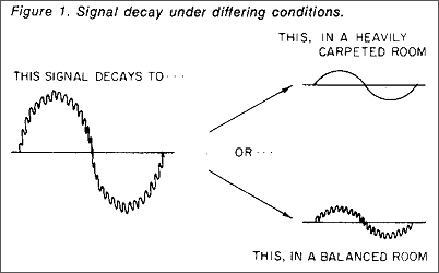
 In the carpeted room we are left with a muddy sound. Since the high frequencies were absorbed quickly. FIGURE I shows the result in a heavily carpeted room. The initial sound consisted of two tones of a low and a high frequency of equal volume. In the balanced room this sound has decayed to a faithful miniaturization of the original, but the heavily carpeted room has eaten up the highs and changed the spectrum from that of the original sound. Note that the high frequency wiggles are gone. We are left with a decayed low-frequency note only, hence the term "muddy sound." If you don't want a muddy reverberation, you must treat the room with materials that absorb low frequencies as quickly as high frequencies. If we had been listening to music, our ears would have heard the new notes, plus the muddy reverberation of past notes, giving the impression of added bass in the room.
Jump to Links
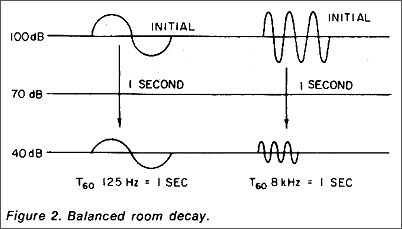
 Can we avoid treating the room acoustically and simply equalize down the bass in the monitor system? No. Equalization only affects the initial amplitude of the sound; it does not change the rate at which it decays. FIGURE 2 shows what happens when an attempt is made to equalize problems like this. Please note that numbers and pictures are exaggerated here for clarity.
In FIGURE 2 we see that the initial amplitude of the low and high frequencies are both 100 dB. The T60 of the balanced room is one second at all frequencies, so a r one second both tones have dropped to 40 dB, which is essentially inaudible. Note that they both fell at the same rate from the same level and crossed the inaudibility threshold at the same time.
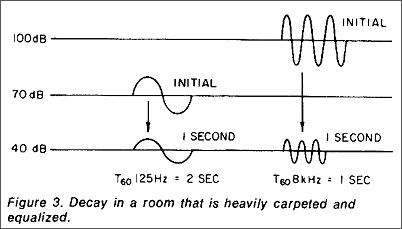
 In the heavily-carpeted room with the muddy reverb, FIGURE 3, we have attempted to compensate by equalizing down the bass. The T60) of the bass is two seconds, and the T60 of the treble is one second. If we equalized down the bass 30 dB, it would start at an initial amplitude of 70 dB and fall 30 dB in the same time that the high frequencies would fall from 100 dB to 40 dB. Therefore both tones would again become inaudible simultaneously. But we have made the reverberation tonal balance correct at one point only, at 40 dB, which is useless because since the decay times are different at low and high frequencies. The tonal balance is changing throughout the decay period. Also, the direct sound is now totally non-flat.
By contrast, the balanced room of FIGURE 2 has a flat direct sound, an unchanged tonal balance for the entire decay period and both frequencies reach inaudibility together through the whole range. Clearly this is a much more desirable situation than that created in the heavily carpeted, heavily equalized room of FIGURE 3. The wonderful result of this balanced room is that a speaker that is flat in an anechoic chamber will sound flat at the mixer's ears, too, without equalization. Jump to Links
Contrary to popular opinion, a real-time analyzer does not display in real time, for if it did our poor slow eyes could not follow it. It integrates the input over a finite time period with a slow decay that makes observing reverberation impossible. On the RTA, the reverb of the room adds to the display of the pink noise, and a nonflat reverb characteristic will add more of some frequencies than others.
For example, on the RTA, our carpeted room with the muddy reverb will add low end to the display, giving the impression that the initial sound is bass heavy and that equalization is needed. The RTA's blind addition of signal and reverb is the root of the problem. RTAs are used with pink noise, which is a static, continuous sound, as compared with music and speech which are impulsive in nature. Impulse sound is defined by its initial level and time history,' and the RTA simply adds level and time history together in a way that our ears do not. Our ears hear the effects, of room reverb during the pauses of music and speech. Pink noise has no such pauses.
How real is this effect in actual control rooms? Of course, reverberation 20, dB or more below initial levels will not add significantly to the curve height on a RTA, but the next 20 dB does. That the reverb is significant in affecting the RTA's display is borne out by the- fact that in a room, with a T60 of 0.2 second, significant reverberant energy exists as close as three feet from the speaker. Obviously this depends upon other factors, most notably speaker Q. But when a speaker whose one foot frequency response of -2 dB becomes -12 dB at 8 feet (this actually occurred in a control room we measured) you can see that the room reflections have a pretty heavy influence.
This wild response was not caused by standing waves. This room was plagued by a non-uniform T60 vs. frequency curve. The ironic part of this story is that the speaker itself is obviously quite flat (-2 dB) and yet the room is giving this speaker a bad reputation (-12 dB). I wonder how many engineers are condemning their innocent speakers!
In addition to all this, equalizing the monitor system makes the important direct sound non-flat! Two rooms, equalized flat, can (and often do) sound different for this reason. Attempting to correct frequency-dependent time decays with initial amplitude equalization is like adding apples and oranges. This basic error occurs regardless of whether you equalize to sine waves, pink noise, or "full spectrum" pulses.
Jump to Links
Properly treating a room is a complex job. What follows is merely a synopsis of common problems and solutions and is not meant to be a do-it-yourself guide to an acoustics diploma. Employing an experienced consultant is a wise decision if your room needs therapy.
Standing waves are a function of room dimensions and shape. Flutter echo is caused by multiple reflections between parallel surfaces. Room modes are room resonances that occur closely spaced in frequency and tend to reinforce their characteristic frequency when it is present in the program material. These problems are minimized by designing a setting with few parallel surfaces, ensuring adequate diffusion and by isolating room-resonant frequencies from each other by choosing optimum room dimension ratios. These are mentioned in Reference 3. Speaker placement can also affect standing waves.
A deep notch, characteristic of a high Q resonator, must be searched out to find out what surface is vibrating. Then stiffen it. These notches show up equally well with RTAs and with sine wave reverb measurements. The need for symmetry and stereo separation must be also kept in mind. These problems, although often severe, lay the groundwork for the room T analysis. With the gross problems out of the way, the absorption is added, subtracted, or modified to provide the desired T60 in each frequency band, usually octave bands. This can be planned in advance to an extent by using tables of absorption coefficients that have been published for various building materials. You multiply the square footage of each material by its coefficient at each frequency, and then you add up the total for each frequency and apply this to a T60 equation such as the Norris-Eyring. But since no one has published the absorption coefficient of your console, you'll need to take measurements of the T60 curve. Some may want a control room with a reverb curve approaching that of a typical living room, or perhaps a flat T60. vs. frequency curve is desired.
Finally, an equalizer, can be used to fine tune the speaker system if its anechoic chamber response needs changing or if it was never tested in a chamber in the first place due to its custom design (often the case in studios). Usually the difference between one-foot and eight-foot frequency response curves points out the degree to which room reverb is playing a part, and here a RTA is handy.
Td sum up, control rooms are not equalizers or filters (though they may appear to be on a RTA screen). They are time-decay absorbers. Do not correct rooms with amplitude changes (equalization); correct their T60 curves instead. Equalizers are useful for fine-tuning of speaker deficiencies that would show up in anechoic measurements, or for electrical modification of a recorded track, etc. When acoustical changes are not possible, as in many sound-reinforcement applications, equalization has the additional use of allowing increases of acoustic gain if applied properly.4
Jump to Links
Other articles by Alan Fierstein in dB Magazine:
Questions?
Please call us at:
212-925-1365
or write to us using our Contact Form.
Use the menu at left to access the rest of our site.
Back to Top
Copyright 2023 Acoustilog®, Inc.